|
|
1-2=4-3
|
1-2=4-3
|
|
1-2:4-3
|
1&2-4&3
|
|---|
|
|
1-2=4-3
|
1-2=4-3
|
|
1-2:4-3
|
1&2-4&3
|
|---|---|---|---|---|---|
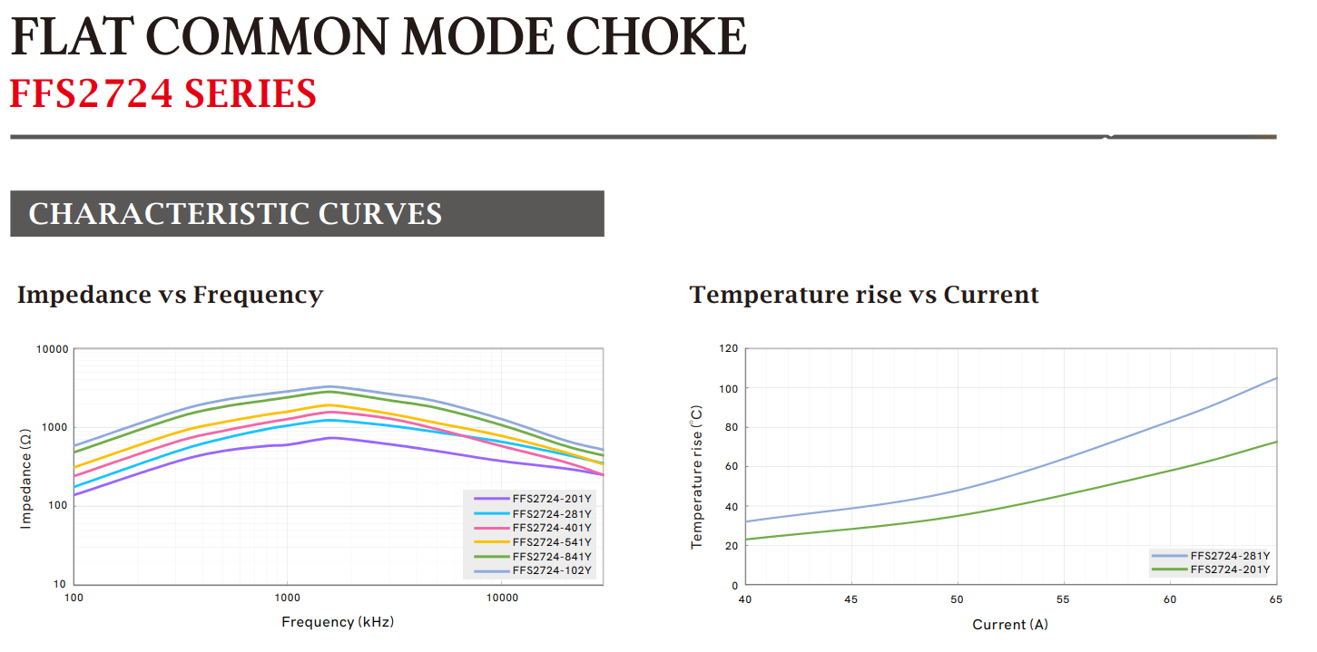
| FFS2724-201Y | 200 | 0.8 | 52 | 1:1 | 200 |
| FFS2724-281Y | 280 | 1.2 | 46 | 1:1 | 200 |
| FFS2724-401Y | 400 | 1.6 | 40 | 1:1 | 200 |
| FFS2724-541Y | 540 | 1.9 | 36 | 1:1 | 200 |
| FFS2724-841Y | 840 | 2.8 | 30 | 1:1 | 200 |
| FFS2724-102Y | 1000 | 3.4 | 25 | 1:1 | 200 |
注:
1、所有电气参数是在 25°C ± 5°C 环境下测量的。
2、电感量在 100 kHz、0 .1 Vrms、 0 ADC 条件下测量 。
3、Irat,是指 25°C 时引起温升约 40°C 的直流电流。温升很大程度上取决于许多因素,包括PCB焊盘走线、尺寸以及其他组件的距离等。因此温升应在特定条件下进行验证。
Copyright © 2026 中光天欣. All Rights Reserved. 蜀ICP备2023041398号-1

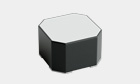


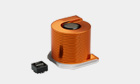


 3D Model